Home › Unlabelled ›
Single Phase Capacitor Motor Wiring Diagram / Ao Smith 2 Speed Motor Wiring Diagram Collection | Wiring ... : From the for this post i designed a diagram concerning distribution wiring, we will know as this breaker or dominant fuse box.
Single Phase Capacitor Motor Wiring Diagram / Ao Smith 2 Speed Motor Wiring Diagram Collection | Wiring ... : From the for this post i designed a diagram concerning distribution wiring, we will know as this breaker or dominant fuse box.. 1 phase & 3 phase wiring. If that isn't a wiring diagram on the bottom of the nameplate look on the inside of the wiring cover you took for lyour pictures of the wire terminations and see if when the motor stopped working i decided to have it wired for 220v and bought new capacitors at grainger both running and starting. Making a single phase induction motor self starting. Some trickery is needed to create a rotating field. 21/03/2011 by lemau 55 comments.
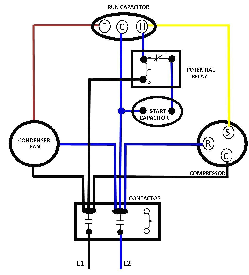
In this split phase motor, the main winding (label 'm') is connected directly to 60 hz ac power, while the other winding (label 'o') is wired in series with a capacitor (c). Electric motor hard starting capacitor wiring & installation installation wiring guide to air conditioning compressor motor & other electric most electrical problems in air conditioning systems are in the compressors and their relays or motor overload switches. Within the diagram is shown. The single phase induction motors are made self starting by providing an additional flux by some additional means. When install a motor using capacitor for starting or running methods,we must sizing the rated of capacitor suitable with motor to get correct starting torque and avoid winding from overheating and can cause a damage.
Top Cause Of Single-Phase Motor Malfunctions | Fluke from dam-assets.fluke.com In a single phase (common. The single phase induction motors are made self starting by providing an additional flux by some additional means. In this split phase motor, the main winding (label 'm') is connected directly to 60 hz ac power, while the other winding (label 'o') is wired in series with a capacitor (c). About 1% of these are capacitors. I am guessing but i would assume that the brown with white tracer is internally shorted to the. Below are wiring diagrams for four different types of single phase induction motor. When install a motor using capacitor for starting or running methods,we must sizing the rated of capacitor suitable with motor to get correct starting torque and avoid winding from overheating and can cause a damage. The top countries of supplier is china, from which the percentage.
Making a single phase induction motor self starting.
The two sections r 1 and r 2 are internally connected in series and one lead. How to wire single phase motor with start/run/permanent capacitors. This capacitor in conjunction with the motor start winding will produce a 90 degree phase shift to produce a rotating field. The single phase motor are those motor which is working one phase and neutral (ground) supply for doing his duty and a 3 phase motor required 3 phase power source. After watching this video you can make the connection of electricity meter at home. An enameled copper wire is wounded on the top core followed by the bottom one and two ends are taken to one side as shown in the figure. The above diagram is a complete method of single phase motor wiring with circuit breaker and contactor. Once the motor is spinning and has inertia, a centrifugal switch opens and the capacitor network is disconnected from the primary motor windings. Applications of single phase induction motors: Within the diagram is shown. The example for this case is the electric fan we see in our daily life, which is a capacitor start and. In this split phase motor, the main winding (label 'm') is connected directly to 60 hz ac power, while the other winding (label 'o') is wired in series with a capacitor (c). Electric motor hard starting capacitor wiring & installation installation wiring guide to air conditioning compressor motor & other electric most electrical problems in air conditioning systems are in the compressors and their relays or motor overload switches.
The above diagram is a complete method of single phase motor wiring with circuit breaker and contactor. Single phase electrical meter or single phase energy meter. A capacitor start motors are a single phase induction motor that employs a capacitor in the auxiliary winding circuit to produce a greater phase difference between the current in the main and the auxiliary windings. About 1% of these are capacitors. Within the diagram is shown.
Single Phase Motor Wiring Diagram With Capacitor | Wiring ... from annawiringdiagram.com Electric fans in the home. 3 phase 400v motor run on 230v single phase supply. Ceiling fan capacitor connection diagram. The vast majority of motors powered by the household or light industrial mains supply are single phase. The figure below shows the connection diagram of a capacitor start motor. About 1% of these are capacitors. Single phase electrical meter or single phase energy meter. How to wire single phase motor with start/run/permanent capacitors.
One is starting winding and another is running winding.
21/03/2011 by lemau 55 comments. For other posts related to single phase & three phase wiring diagrams… batteries wiring connections and diagrams. Alibaba.com offers 158 single phase capacitor motor wiring diagram products. 3 phase 400v motor run on 230v single phase supply. How to wire single phase motor with start/run/permanent capacitors. 1 phase & 3 phase wiring. The example for this case is the electric fan we see in our daily life, which is a capacitor start and. A single phase induction motor is an electric motor that operates on a single waveform of alternating current. The two sections r 1 and r 2 are internally connected in series and one lead. The above diagram is a complete method of single phase motor wiring with circuit breaker and contactor. Within the diagram is shown. When install a motor using capacitor for starting or running methods,we must sizing the rated of capacitor suitable with motor to get correct starting torque and avoid winding from overheating and can cause a damage. Air compressor capacitor wiring diagram before you call a ac repair man visit my blog for some tips on how to save thousands in ac repairs.
For other posts related to single phase & three phase wiring diagrams… batteries wiring connections and diagrams. You can observe this difference in flux direction on diagrams. • switch any two of the motor phase wires. Making a single phase induction motor self starting. This capacitor in conjunction with the motor start winding will produce a 90 degree phase shift to produce a rotating field.
220 Motor Wiring Diagram - Detailed Schematic Diagrams from strategiccontentmarketing.co One is starting winding and another is running winding. Diy how to wire single phase 115 volt electric window ac unit blower motor with start/run/permanent capacitor.wire for. The above diagram is a complete method of single phase motor wiring with circuit breaker and contactor. The phase shift can be achieved by connecting a resistance, inductance or capacitance in series with the starting winding. In this video you'll find out how to connect three phase motor to single. About 1% of these are capacitors. 10 hp motor capacitor bank circuit wiring diagram imgi67.tinypic.com/28jlmpc.png/img amps dropped in half after rewire, corroded wires were causing the mains circuit breaker to trip!! Most single phase motors can be reversed by interchanging #5 lead with #8 lead single phase capacitor start/capacitor run.
The above diagram is a complete method of single phase motor wiring with circuit breaker and contactor.
Electronic starter for single phase motor is used for protecting motor from over currents and different starter methods protection scheme of single phase induction motor. Single phase electrical meter or single phase energy meter. 10 hp motor capacitor bank circuit wiring diagram imgi67.tinypic.com/28jlmpc.png/img amps dropped in half after rewire, corroded wires were causing the mains circuit breaker to trip!! There a capacitor is used in series with starting winding, it defines the direction of rotation. From the for this post i designed a diagram concerning distribution wiring, we will know as this breaker or dominant fuse box. The above diagram is a complete method of single phase motor wiring with circuit breaker and contactor. Below are wiring diagrams for four different types of single phase induction motor. Electric fans in the home. In addition to the main winding or running winding, the stator of single phase induction motor carries another winding called auxiliary winding or starting winding. The single phase induction motors are made self starting by providing an additional flux by some additional means. Applications of single phase induction motors: • switch any two of the motor phase wires. A single phase induction motor is an electric motor that operates on a single waveform of alternating current.